Contents
- Concept Generation
- Material Selection
- Concept Description
- Parameter Analysis
- Final Design
Concept Generation
In concept generation, our team first carried out functional decomposition, wherein the overall problem is identified and decomposed into smaller and more easily manageable parts.
a) Overall Function
To smooth rotational movements to a phone camera subject to disturbances during filming and provide a pleasant user experience
b) Sub Functions
- To provide enough electrical energy to power microcontrollers, motors and sensors
- To provide mechanical support for frame, microcontrollers, motors, sensors and camera
- To allow modal control (horizontal vs vertical)
- To secure camera phone to frame
- To allow users easy assembly and disassembly of frame
- To sense the 3-axis positional changes of camera
- To differentiate between intentional and unintentional movement
- To compensate for disturbances to camera
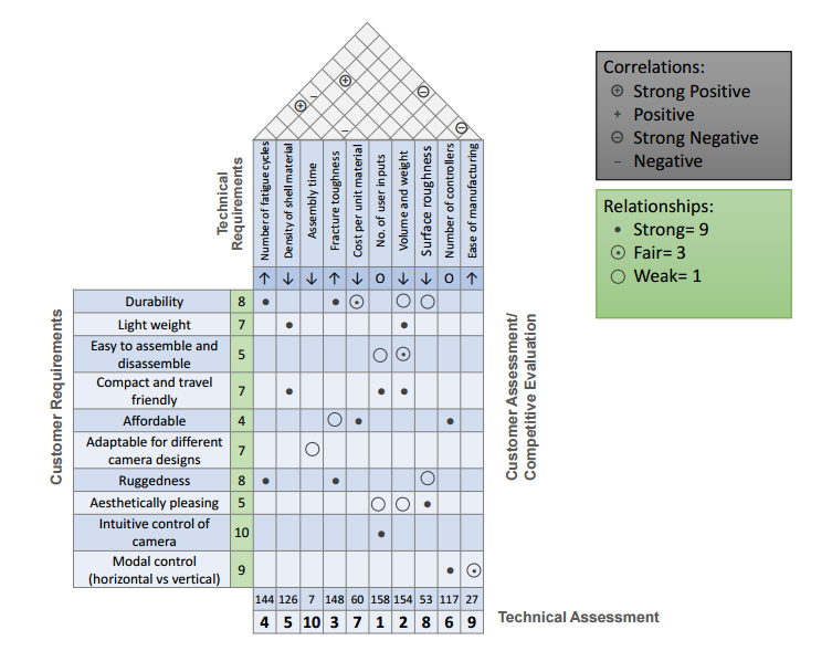
The following is the Quality Function Deployment (QFD) chart that we derived by analyzing customer and technical requirements:
Material Selection
Customer requirements were translated to technical requirements, leading to the choice of our design materials. The following section explains how combined customer and technical requirements are fulfilled by the specifications of our design. (Components clockwise from top left)
Customer requirements were translated to technical requirements, leading to the choice of our design materials. The following section explains how combined customer and technical requirements are fulfilled by the specifications of our design. (Components clockwise from top left)

6061-T6 Aluminum Square Bars
Fulfilled customer requirements: Durability/Ruggedness, Lightweight, Affordable, Compact and Travel friendly
Fulfilled technical requirements: High number of fatigue cycles, Appropriate volume and weight, No. of user inputs
Further justification for selection: One of the most available materials in the market with affordable pricing. Good strength. Can be easily machined in the lab.
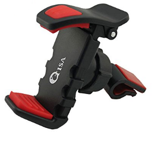
OTISA Portable Universal Car Air Vent Phone Holder Mount
Fulfilled customer requirements: Adaptable for different camera designs, Aesthetically pleasing
Fulfilled technical requirements: N/A
Further justification for selection: Readily available online and adaptable for different cameras
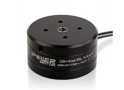
iPower GBM4108H-200T & Gimbal Motor
Fulfilled customer requirements: Intuitive control of camera, Modal control (horizontal and vertical)
Fulfilled technical requirements: No. of user inputs, No. of controllers
Further justification for selection: Specifically designed for gimbals and sufficient camera range of 200-500 and 600-1200 grams depending on the weight that each motor is assigned to.
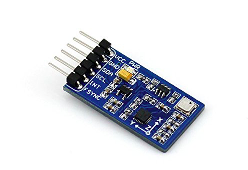
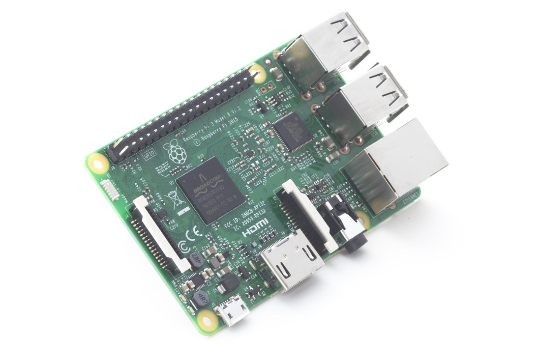
Arduino Uno, Raspberry Pi 3, Waveshare IMU
Fulfilled customer requirements: Intuitive control of camera, Compact and Travel friendly, Lightweight
Fulfilled technical requirements: No. of controllers
Further justification for selection: The powerful microprocessors enable proper working and communication between motors and sensors. Small versions reduce total weight. The Inertial Measurement Unit (IMU) serves to sense the movement and communicates with microprocessors.
Fulfilled customer requirements: Durability/Ruggedness, Lightweight, Affordable, Compact and Travel friendly
Fulfilled technical requirements: High number of fatigue cycles, Appropriate volume and weight, No. of user inputs
Further justification for selection: One of the most available materials in the market with affordable pricing. Good strength. Can be easily machined in the lab.
OTISA Portable Universal Car Air Vent Phone Holder Mount
Fulfilled customer requirements: Adaptable for different camera designs, Aesthetically pleasing
Fulfilled technical requirements: N/A
Further justification for selection: Readily available online and adaptable for different cameras
iPower GBM4108H-200T & Gimbal Motor
Fulfilled customer requirements: Intuitive control of camera, Modal control (horizontal and vertical)
Fulfilled technical requirements: No. of user inputs, No. of controllers
Further justification for selection: Specifically designed for gimbals and sufficient camera range of 200-500 and 600-1200 grams depending on the weight that each motor is assigned to.
Arduino Uno, Raspberry Pi 3, Waveshare IMU
Fulfilled customer requirements: Intuitive control of camera, Compact and Travel friendly, Lightweight
Fulfilled technical requirements: No. of controllers
Further justification for selection: The powerful microprocessors enable proper working and communication between motors and sensors. Small versions reduce total weight. The Inertial Measurement Unit (IMU) serves to sense the movement and communicates with microprocessors.
Concept Description
a) Overview
The goal of the self-stabilizing gimbal is straight forward. Given a disturbance in 3 axis (Yaw / Pitch / Roll), the gimbal needs to sense these changes and thereby implement a counter rotation that restores the end effector (the camera) to its original position. To date, many commercial gimbals have tackled this problem using 3 servo motors, an accelerometer and a gyroscope. The servos are oriented orthogonal to each other, allowing for 3 axis correction. The readings from the accelerometer and gyroscope are processed by a microprocessor which determines angular displacements and commands each servo respectively.
Sensing actual angular displacements is a difficult task. The signal received from the sensors can be noisy or biased, with errors building up overtime. To address this issue, our group has decided to implement encoders that provide relative positional tracking and Kalman filtering. A Kalman filter determines the state of a system at time t based on its previous state at time t-1 and observed readings from sensors. This helps reduce noisy inputs for a more accurate sensing of the camera’s actual position. Once the camera has been tracked, we can implement a closed loop PID controller to restore it to its original position.
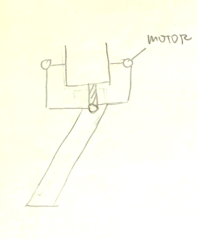
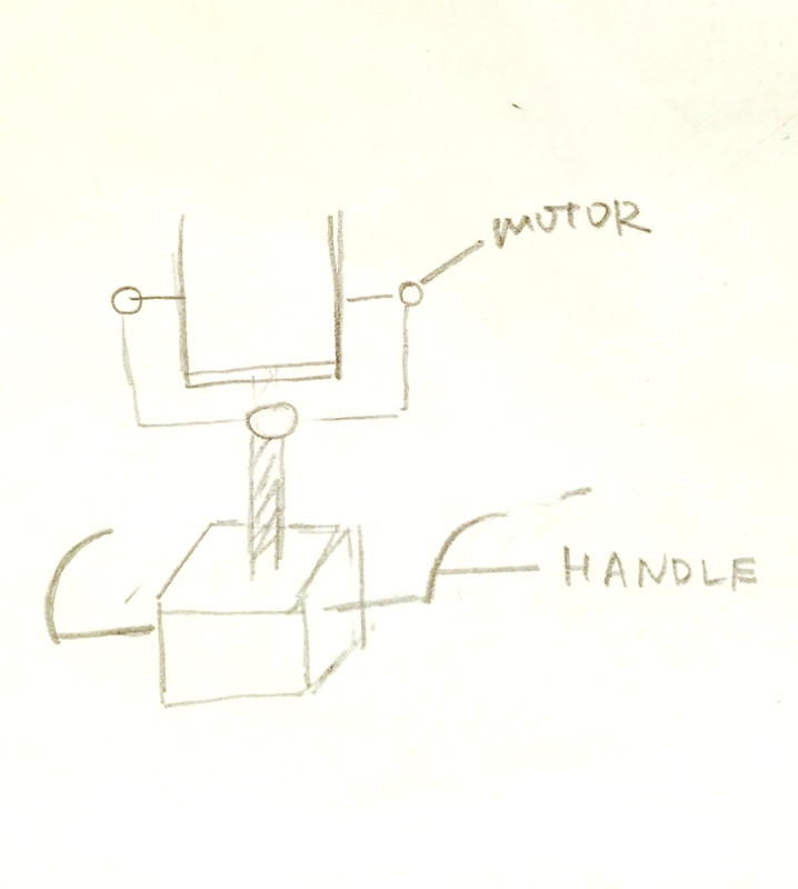
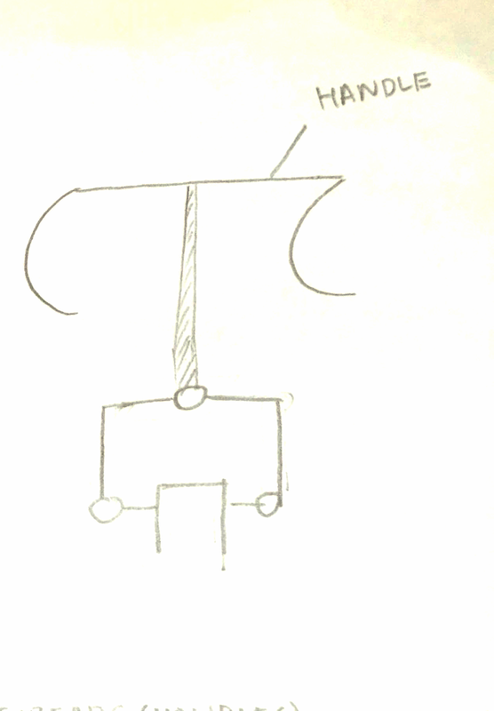
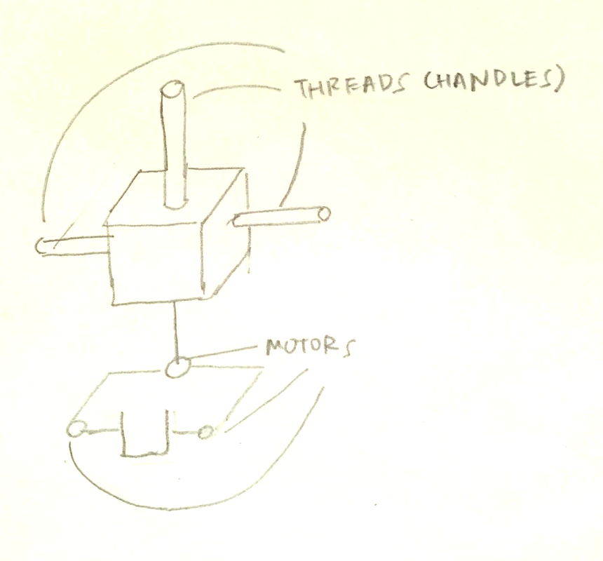
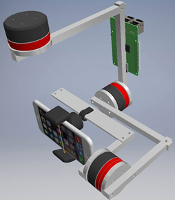
Our first rendition of our gimbal is represented below. There are three servo motors mounted on three orthogonal axis that allows for 3 axis compensation. The Raspberry Pi unit is in green at the back.
a) Overview
The goal of the self-stabilizing gimbal is straight forward. Given a disturbance in 3 axis (Yaw / Pitch / Roll), the gimbal needs to sense these changes and thereby implement a counter rotation that restores the end effector (the camera) to its original position. To date, many commercial gimbals have tackled this problem using 3 servo motors, an accelerometer and a gyroscope. The servos are oriented orthogonal to each other, allowing for 3 axis correction. The readings from the accelerometer and gyroscope are processed by a microprocessor which determines angular displacements and commands each servo respectively.
Sensing actual angular displacements is a difficult task. The signal received from the sensors can be noisy or biased, with errors building up overtime. To address this issue, our group has decided to implement encoders that provide relative positional tracking and Kalman filtering. A Kalman filter determines the state of a system at time t based on its previous state at time t-1 and observed readings from sensors. This helps reduce noisy inputs for a more accurate sensing of the camera’s actual position. Once the camera has been tracked, we can implement a closed loop PID controller to restore it to its original position.
Our first rendition of our gimbal is represented below. There are three servo motors mounted on three orthogonal axis that allows for 3 axis compensation. The Raspberry Pi unit is in green at the back.
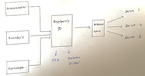
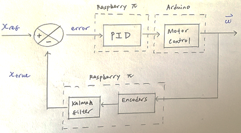
b) System integration
The flow of information from the sensors to the micro processing unit and back is depicted in the diagram below. The readings from the accelerometer and gyroscope are processed by the Raspberry Pi 3, running on Raspbian OS. The Raspberry Pi then sends a signal to the Arduino which directly controls the servo motors.
The flow of information from the sensors to the micro processing unit and back is depicted in the diagram below. The readings from the accelerometer and gyroscope are processed by the Raspberry Pi 3, running on Raspbian OS. The Raspberry Pi then sends a signal to the Arduino which directly controls the servo motors.
c) Raspberry Pi 3
Our group hypothesizes that the workload on a single Arduino microprocessor is too heavy and a more robust microprocessor is required to support parallel processing of sub tasks as well as a comprehensive support library. We thus decouple our project into 2 layers. The higher layer functionality involves accurately determining the state of the camera. The lower layer involves direct servo motor control. We assigned the higher layer control to the Raspberry Pi 3 and the lower layer control to the Arduino.
The Raspberry Pi 3 (with Raspbian OS) runs on a Linux environment and is mainly used in higher level control of systems. It supports Python libraries with C++ bindings which are computationally fast and efficient. With Python, we can easily perform parallel processing using the threading library, Kalman filtering using the pykalman library and a PID control using the pypid library. This greatly alleviates the implementation of complicated algorithms which might be full of bugs. The Raspberry Pi has IO ports that allows direct sensing of Accelerometer and Gyroscope readings as well as communication with the Arduino.
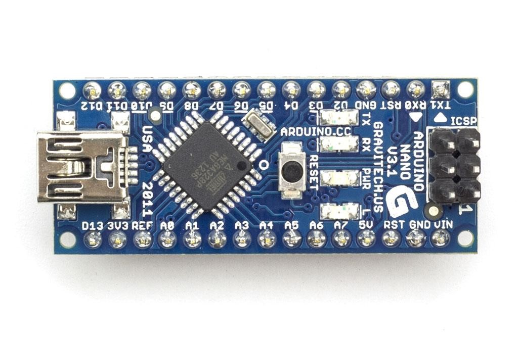
d) Arduino
Low level control of servo motors is done using the Arduino. The Arduino is a 5V processor that has a total of 22 Analog and Digital pins. The Arduino receives a signal from the Raspberry Pi and concurrently controls the servo motor.
e) Kalman Filtering
The fundamental assumption that validates the use of Kalman Filtering is that all measurements have a certain degree of noise. It is common to model this noise as a Gaussian distributed function with mean 0 and variance Qt. This noise gives rise to inaccurate and jittery readings of the camera’s position in Cartesian space. In addition, the current state of the camera can also be a function of its previous states as well as a control input Ut. In our case, this control input can be the sensing from our accelerometer, gyroscope and encoders.
Our group hypothesizes that the workload on a single Arduino microprocessor is too heavy and a more robust microprocessor is required to support parallel processing of sub tasks as well as a comprehensive support library. We thus decouple our project into 2 layers. The higher layer functionality involves accurately determining the state of the camera. The lower layer involves direct servo motor control. We assigned the higher layer control to the Raspberry Pi 3 and the lower layer control to the Arduino.
The Raspberry Pi 3 (with Raspbian OS) runs on a Linux environment and is mainly used in higher level control of systems. It supports Python libraries with C++ bindings which are computationally fast and efficient. With Python, we can easily perform parallel processing using the threading library, Kalman filtering using the pykalman library and a PID control using the pypid library. This greatly alleviates the implementation of complicated algorithms which might be full of bugs. The Raspberry Pi has IO ports that allows direct sensing of Accelerometer and Gyroscope readings as well as communication with the Arduino.
d) Arduino
Low level control of servo motors is done using the Arduino. The Arduino is a 5V processor that has a total of 22 Analog and Digital pins. The Arduino receives a signal from the Raspberry Pi and concurrently controls the servo motor.
e) Kalman Filtering
The fundamental assumption that validates the use of Kalman Filtering is that all measurements have a certain degree of noise. It is common to model this noise as a Gaussian distributed function with mean 0 and variance Qt. This noise gives rise to inaccurate and jittery readings of the camera’s position in Cartesian space. In addition, the current state of the camera can also be a function of its previous states as well as a control input Ut. In our case, this control input can be the sensing from our accelerometer, gyroscope and encoders.
f) PID controller
The PID controller is a common controller used in closed loop systems. It serves as a filter before the plant, which is the main controller of the servo motors, and helps attenuate the error between the actual and desired input signal. In our case, the error could be the difference between the desired camera orientation at Roll / Pitch / Yaw of 0 rad and the current camera’s orientation. The controller has 3 parameters that the user can vary. Kp pertains to the proportionality constant, Ki pertains to the integrator and Kd pertains to the derivative. Our choice of and is essential in determining the characteristic profile of the error function.
The PID control is performed at the high level controls using the Raspberry Pi, with support from the pypid library. The idea is to correct the displaced camera back to its neutral position, denoted by xref. xref is calibrated at the very start and it is the orientation which the gimbal will intend to achieve at any point in time. When the Raspberry Pi senses an angular displacement, an error signal is triggered which propagates through the respective channels seen below and results in a velocity of the motor.
Parameter Analysis
The FilmIt Gimbal was created by our team to be a tool that could be used by everyone, not only video professionals. In generating our design, this was our main concern. For that reason we wanted our product to work like a selfie stick. Our technical decisions were thus made with this idea in mind.
a) Material and Shape
A major concern was the manufacturing of the gimbal. When the group was creating its concept, we decided that we wanted it to be as simple to manufacture as possible. We decided that the most effective way to accomplish this was to use square aluminum bars. Such bars can be easily found online, which was also a good reason to support our choice. Aluminum proved itself as a suitable choice of material due to its low density along with its ease to process using the machinery that we have available in the Mechanical Engineering Machine Shop. The choice of square shape instead of round shape was also due to the ease of manufacture and simplicity in assembling the parts.
The holding stick of FilmIt Gimbal generated a lot of discussions in our group. After the first Design Review, the ME102B panel suggested the idea of using 3D printing as one of our manufacturing processes. This process would allow us to produce a light and resistant piece. For that reason we decided to use 3D printing to manufacture the holding stick of the product.
b) Design & Dimensions
Mobility of the parts is a very important aspect of the Gimbal. The design has three degrees of freedom. The smartphone, along with the IMU, is located where the 3 axes intersect. The function of the IMU is to provide the angular position of the phone and send this information to the Raspberry Pi in order for it to correct the movements.
Regarding the design of the joints and connections, the group made a base to have a general idea of the final geometry, then purchased the parts which did not require manufacturing (motors, raspberry pi, IMU and encoders). With these parts in hand, the group finalized the CAD detailing the connections and assemblies.
As for the dimensions of the parts, the group based the soundness of the design not on the safety factors for stress, but instead on the bending displacement under operating conditions. The designed structure is stiff enough to not allow a large displacement of the internal parts, and should at the same time be very safe to bear the associated stresses. Because of its complex shape, our group chose not to analyze our gimbal as a model with equations, but by using a Finite Element analysis. It can be seen in the following images that the safety factor is greater than 15 and the largest displacement is 0.3mm. This last number is a reasonable value for a gimbal and shows that 0.5 inches square bars are acceptable for manufacturing the frame of the product.
Final Design
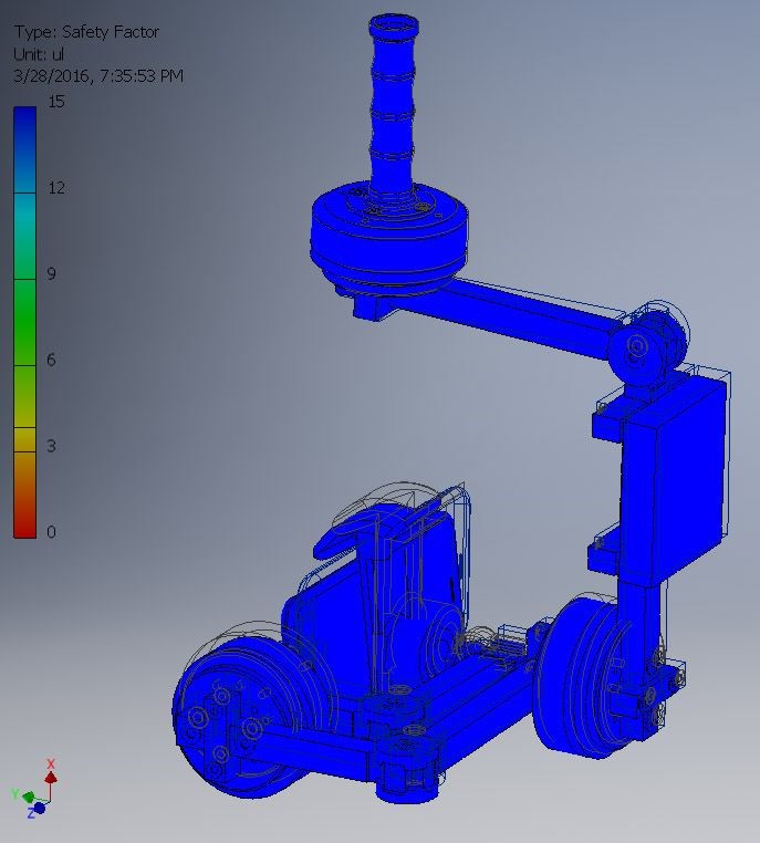
FEM Stress Analysis – Stress safety factors ~ 15
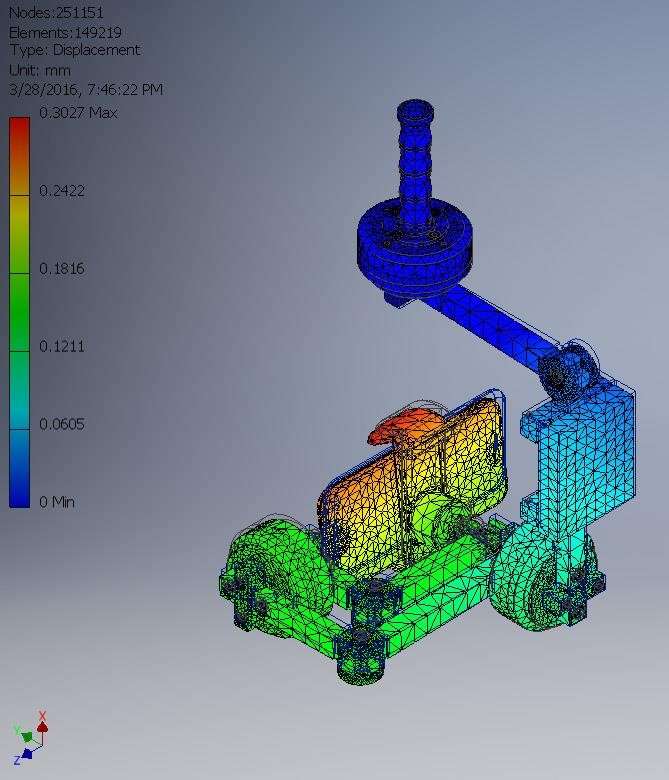
FEM Displacement Analysis
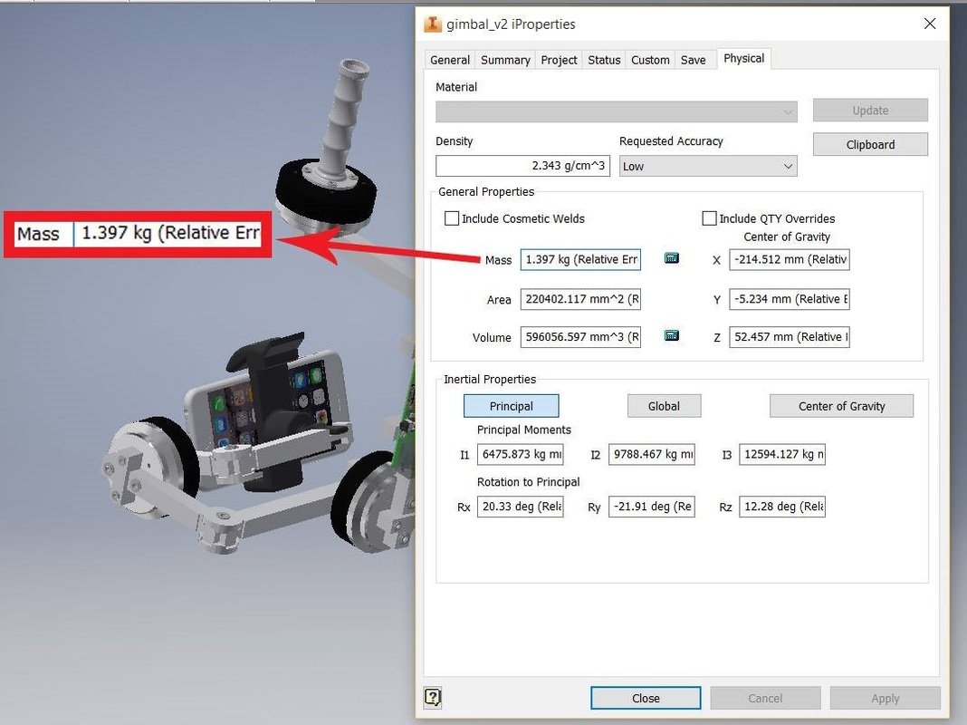
Total weight of the Gimbal – 1.397kg
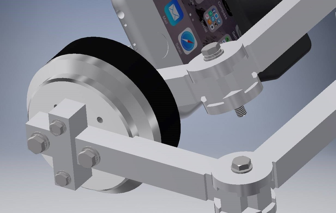
Arm-Motor Bolt Joint
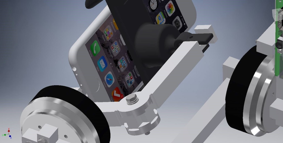
Phone Holder Attachment
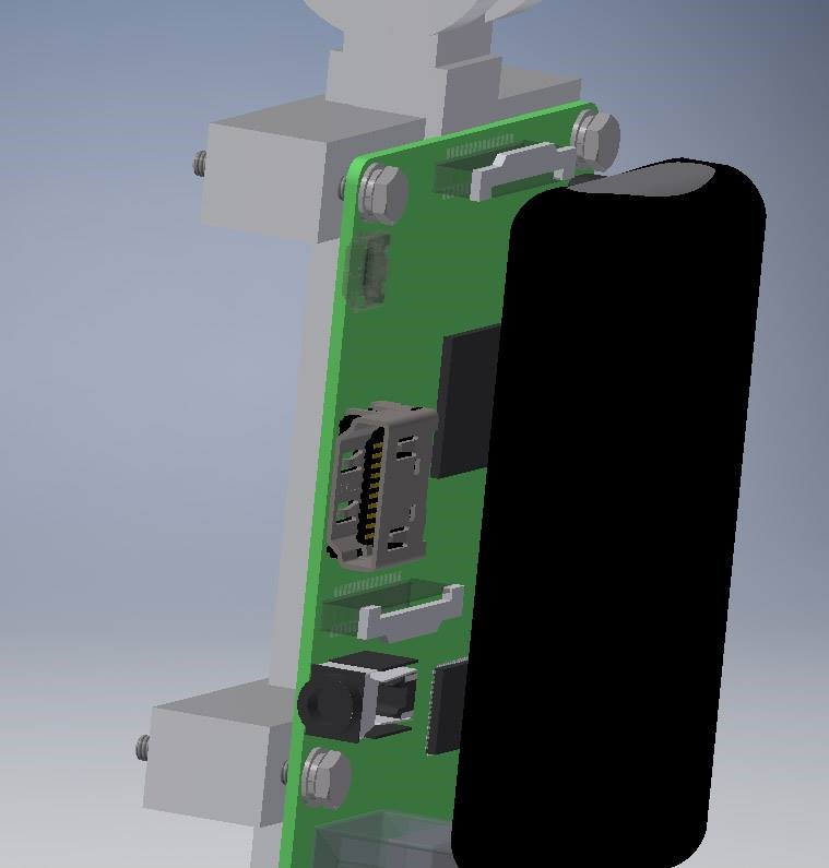
Raspberry Pi
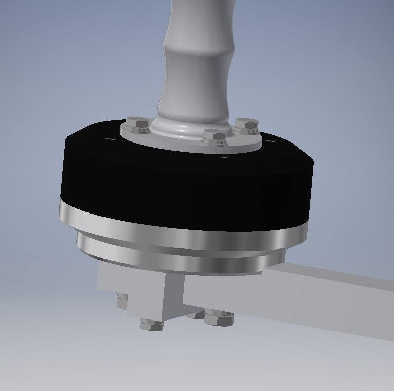
Base Motor and Adjoining Selfie Stick
